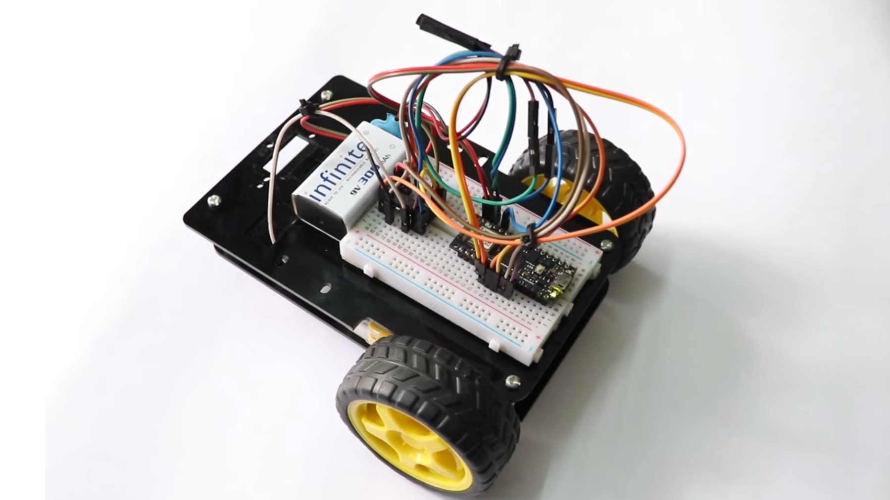
Building your first robot can sound intimidating. The word “robotics” tends to summon images of advanced laboratories, complicated mathematics, and machines plotting to replace humanity before lunch. Fortunately, a beginner-friendly two-wheeled Arduino robot is much less dramatic. It is essentially a small rolling platform with two motors, an Arduino board, a motor driver, and just enough code to make it explore the kitchen floor.
This project is an excellent introduction to electronics, mechanical assembly, Arduino programming, pulse-width modulation, and differential steering. The Arduino Uno is especially suitable for beginners because it provides a familiar development environment, six PWM-capable digital pins, ample connections for basic sensors, and a large ecosystem of tutorials and examples.
By the end of this guide, you will have a working two-wheeled Arduino robot that can move forward, reverse, turn, spin in place, and stop without crashing into every chair leg in the houseunless you program it to do so.
What Is a Two-Wheeled Arduino Robot?
A two-wheeled Arduino robot is a small mobile robot powered by two independently controlled DC motors. One motor drives the left wheel, and the other drives the right wheel. A caster wheel or smooth skid supports the remaining weight and keeps the chassis balanced.
This arrangement is called differential drive. Instead of steering with a separate mechanism, the robot changes direction by varying the speed and direction of its two wheels.
- Both wheels moving forward at the same speed make the robot travel straight.
- The left wheel moving faster causes the robot to curve right.
- The right wheel moving faster causes it to curve left.
- One wheel moving forward while the other reverses makes the robot spin in place.
- Both wheels stopping gives the furniture a much-needed break.
Commercial educational platforms from SparkFun and Pololu use the same basic combination of two geared motors, two driven wheels, and a caster. The design is popular because it is mechanically simple, maneuverable, and easy to expand with sensors or wheel encoders.
Parts and Tools You Will Need
Essential Electronic Components
- One Arduino Uno R3 or compatible board
- One TB6612FNG dual motor driver module
- Two 3-volt to 6-volt geared DC motors
- Two matching wheels
- One two-wheel robot chassis
- One caster wheel
- One four-AA battery holder with switch
- Four rechargeable NiMH AA batteries
- One small USB power bank or suitable regulated 5-volt supply for the Arduino
- Male-to-female jumper wires
- Short hookup wires for the motors
Recommended Tools
- Small Phillips screwdriver
- Wire cutters and strippers
- Soldering iron and solder
- Multimeter
- Double-sided foam tape or nylon standoffs
- Zip ties for cable management
A multimeter is not mandatory, but it can quickly reveal reversed polarity, weak batteries, loose grounds, and other electrical mysteries. Without one, troubleshooting sometimes becomes a ceremony involving random wire wiggling and increasingly emotional conversations with the robot.
Why You Need a Motor Driver
The Arduino controls logic signals, but it should not power the drive motors directly. Small DC motors can draw much more current than an Arduino input/output pin can safely supply, especially when starting, stopping, or becoming stalled.
A motor driver acts as a power interface between the Arduino and the motors. It receives low-current control signals from the Arduino and switches the higher motor current from a separate battery supply. Its internal H-bridges also let the Arduino reverse the polarity delivered to each motor, allowing forward and backward movement.
The TB6612FNG is a practical choice for a small beginner robot because it controls two DC motors, supports speed and direction control, and is rated for approximately 1.2 amps of continuous current per channel under appropriate conditions. Traditional L298N boards can also work, but they are larger and generally waste more voltage as heat.
Check Motor Current Before Connecting Anything
Do not select a motor driver based only on the motor’s normal running current. Find the motor’s stall current, which is the current it may draw when the shaft cannot turn. A robot wheel trapped against a wall can temporarily place the motor near this condition.
Your driver should tolerate the expected operating current and short startup peaks. If the motors become hot, the driver repeatedly shuts down, or the Arduino resets during acceleration, current demand may be higher than your power system can handle.
Assembling the Robot Chassis
Step 1: Install the Motors
Attach the two geared motors to opposite sides of the chassis. Make sure their shafts are aligned and positioned at the same height. Tighten the brackets enough to prevent movement, but do not crush a lightweight plastic motor housing.
Step 2: Attach the Wheels
Press the wheels onto the motor shafts. Both wheels should rotate freely without rubbing against the chassis. If one wheel sits farther outward than the other, the robot may wobble or drift.
Step 3: Install the Caster
Mount the caster at the front or rear of the chassis. The exact location is flexible, although placing it opposite the heaviest electronics usually produces better balance. A properly arranged differential-drive chassis can rotate in place because its driven wheels sit across the main turning axis.
Step 4: Mount the Electronics
Install the Arduino, motor driver, battery holder, and power bank using screws, standoffs, hook-and-loop tape, or foam tape. Keep the battery pack low and near the center. A low center of gravity makes the robot less likely to tip during sudden turns.
Leave access to the Arduino USB port. Otherwise, every code update may require partially dismantling the robot, which is a surprisingly efficient way to turn a ten-minute experiment into an afternoon project.
Wiring the Arduino Robot
TB6612FNG to Arduino Connections
| TB6612FNG Pin | Arduino Connection | Purpose |
|---|---|---|
| VCC | 5V | Logic power |
| GND | GND | Common ground |
| STBY | Digital pin 9 | Enables the driver |
| PWMA | Digital pin 5 | Left motor speed |
| AIN1 | Digital pin 2 | Left motor direction |
| AIN2 | Digital pin 4 | Left motor direction |
| PWMB | Digital pin 6 | Right motor speed |
| BIN1 | Digital pin 7 | Right motor direction |
| BIN2 | Digital pin 8 | Right motor direction |
Motor and Battery Connections
- Connect the left motor to A01 and A02.
- Connect the right motor to B01 and B02.
- Connect the motor battery positive wire to VM.
- Connect the motor battery negative wire to GND.
- Connect the Arduino ground to the same common ground.
- Power the Arduino through its USB port using a USB power bank.
The shared ground is essential because the Arduino and motor driver need the same electrical reference for control signals. However, the motors should receive power through the driver’s motor supply input rather than from an Arduino output pin.
Using a separate motor supply is often more reliable because motors create electrical noise and sudden current demands. An inadequate shared supply can cause voltage dips and unexpected Arduino resets. Adafruit and SparkFun motor-control documentation both emphasize careful power selection and, in many setups, recommend separating logic power from motor power.
Arduino Code for the Two-Wheeled Robot
Install the Arduino IDE, connect the Uno with a USB cable, select the correct board and port, and upload the following sketch. This example moves forward, stops, spins right, reverses, and stops again.
How the Code Controls Speed
The analogWrite() function creates a PWM signal on supported Arduino pins. On a typical Uno, values range from 0 to 255. A value of 0 produces no drive output, while 255 represents the maximum commanded duty cycle. Intermediate values rapidly switch the motor voltage on and off, changing the motor’s average power and speed.
The robot code uses positive numbers for forward movement and negative numbers for reverse movement. This allows one function to control direction and speed without creating separate functions for every possible maneuver.
Why One Motor Uses Reversed Polarity
The two motors face opposite directions when mounted on the chassis. As a result, applying identical electrical polarity may make one wheel rotate forward while the other rotates backward.
The example compensates with RIGHT_POLARITY = -1. If your robot spins when it should move straight, change one polarity constant or swap the two wires connected to that motor. Motor-control documentation commonly recommends swapping motor leads when the software’s definition of forward does not match the physical installation.
Testing the Robot Safely
Perform the First Test With the Wheels Raised
Place the robot on a small box so its wheels do not touch the table. Turn on the motor battery and Arduino power. Confirm that both wheels rotate in the expected directions.
This simple precaution prevents your freshly built robot from launching itself toward a laptop, coffee mug, pet, or other object with strong opinions about being struck by experimental machinery.
Test Each Motor Separately
If the robot behaves unpredictably, temporarily call driveRobot(150, 0) to test the left motor. Then use driveRobot(0, 150) to test the right motor. Check the corresponding wiring if one side does not move.
Begin With Moderate Speed
Start with PWM values between approximately 120 and 180. At very low values, a motor may hum without turning because it lacks enough torque to overcome friction. At full speed, the robot may move too quickly for convenient troubleshooting.
Calibrating the Robot to Drive Straight
Two inexpensive motors rarely spin at exactly the same speed. Differences in gearboxes, wheel friction, chassis alignment, battery wiring, and weight distribution can cause the robot to curve even when both motors receive the same PWM command.
To compensate, reduce the command sent to the faster motor. For example:
Test the robot over a measured distance of six to ten feet. Adjust one side in increments of three to five PWM units until it travels reasonably straight.
This method is open-loop calibration. It works well for a basic project, but performance can change as the battery discharges or the floor surface changes. Wheel encoders provide a more advanced solution by measuring wheel rotation, allowing the software to correct speed differences automatically. SparkFun and Pololu robot platforms use encoder feedback for measuring wheel speed, distance, and motion.
Common Problems and Solutions
The Motors Do Not Move
- Confirm that the STBY pin is HIGH.
- Check the motor battery voltage.
- Verify that Arduino ground and motor-driver ground are connected.
- Make sure the motor wires are firmly attached.
- Check that the PWM pins match the code.
The Arduino Resets When the Motors Start
This usually indicates a power problem or motor noise. Try a fresh motor battery, separate the motor and Arduino power sources, shorten motor wires, and verify all ground connections. Small ceramic capacitors installed across motor terminals may also help suppress electrical noise.
One Motor Runs but the Other Does Not
Swap the motor connections between channel A and channel B. If the problem moves with the motor, inspect the motor or its wiring. If the same driver channel remains inactive, inspect its control pins and module connections.
The Driver Becomes Hot
Disconnect power immediately. Check for short circuits, jammed wheels, excessive motor voltage, or motors that draw more current than the driver can safely handle.
The Robot Turns the Wrong Way
A differential-drive robot turns based on relative wheel movement. To turn right, slow or reverse the right wheel while keeping the left wheel moving forward. If the result is backward, reverse one motor’s polarity constant.
Beginner-Friendly Upgrades
Add an Ultrasonic Sensor
An HC-SR04-style ultrasonic sensor can measure the distance to nearby objects. Mount it at the front and program the robot to stop, reverse, and turn when an obstacle is detected.
Create a Line-Following Robot
Install two or three infrared reflectance sensors beneath the chassis. The Arduino can compare sensor readings and adjust motor speeds to follow a dark line. Two-wheel chassis kits and H-bridge motor drivers are commonly used in educational line-following designs.
Add Bluetooth Control
A Bluetooth serial module can let a smartphone send commands such as forward, reverse, left, right, and stop. Build manual control only after the basic motor functions work correctly. Adding wireless communication before testing the drivetrain creates twice as many possible bugs and approximately four times as much confusion.
Install Wheel Encoders
Encoders count wheel or motor-shaft movement. They make it possible to estimate distance, compare left and right wheel speeds, execute more accurate turns, and eventually implement closed-loop speed control.
Replace Delays With Nonblocking Timing
The demonstration sketch uses delay() because it is easy to understand. A more capable robot should use millis()-based timing so it can read sensors and react while a movement is in progress.
Practical Experiences From Building a Beginner Arduino Robot
The first important lesson is that mechanical problems often pretend to be programming problems. When a robot curves left, beginners naturally inspect the code. However, the real cause may be a wheel rubbing against the chassis, a motor bracket sitting slightly crooked, or a battery pack placed too far to one side. Before changing ten lines of software, lift the robot and spin both wheels by hand. They should move smoothly and feel similar.
Another lesson is to test the project in layers. Start by uploading a simple sketch that blinks the Arduino’s built-in LED. This confirms that the board, USB cable, selected port, and development environment are working. Next, test the motor driver without attaching the wheels. Then test each motor independently. Finally, combine the motors into complete robot movements.
This layered approach may feel slower, but it is much faster than assembling everything at once and then confronting a robot that does absolutely nothing. When twenty connections are involved, “nothing happens” is not a particularly helpful diagnostic message.
Wire management matters more than expected. Loose jumper wires can briefly disconnect when the robot turns or hits a bump. The robot may work perfectly while sitting on the table and fail as soon as it starts moving. Secure wires with zip ties or small pieces of tape, and leave enough slack around moving components.
Battery choice also has a noticeable effect. A rectangular 9-volt battery may appear convenient, but many common versions are poorly suited to powering two drive motors because they cannot sustain the required current. Rechargeable AA cells generally provide better current delivery for a small robot. Always match the battery voltage to the ratings of the motors and driver.
The next lesson is that equal PWM values do not guarantee equal wheel speed. Even motors from the same package can behave differently. One may begin moving at a PWM value of 85 while the other refuses to cooperate until 105. Record the lowest reliable starting value for each motor and use those measurements when calibrating movement.
Turning times also depend on the surface. A 600-millisecond spin may produce an almost perfect 90-degree turn on smooth tile but only 65 degrees on carpet. Wheel traction, caster friction, battery voltage, and robot weight all affect timed turns. Treat delay-based turning as an approximation rather than precision navigation.
A physical power switch is an underrated upgrade. Without one, stopping an out-of-control robot may require grabbing it and pulling out a battery wire while the wheels continue spinning. A clearly accessible switch provides a much calmer emergency stop.
It is also helpful to add small status LEDs or Serial Monitor messages. Print commands such as “FORWARD,” “TURNING RIGHT,” and “STOPPED” while testing. If the software says “FORWARD” but the robot spins, the problem is probably motor polarity or wiring rather than decision logic.
Finally, resist the temptation to install every sensor immediately. A reliable robot that moves forward and turns correctly is a successful first milestone. Add one feature at a time, test it, and preserve a working copy of the previous program. This habit prevents a common beginner experience: adding one exciting feature and accidentally converting a functioning robot into a very expensive paperweight.
Conclusion
A two-wheeled Arduino robot is one of the most rewarding beginner electronics projects because it turns basic code into visible movement. You learn how an Arduino sends control signals, how an H-bridge changes motor direction, how PWM adjusts speed, and how differential drive allows a robot to turn without a steering mechanism.
Begin with a simple chassis, a suitable dual motor driver, separate motor power, and a shared ground. Test each subsystem independently, calibrate the two motors, and avoid adding advanced sensors until the drivetrain works reliably.
Once the basic robot is rolling, the same platform can become an obstacle-avoiding robot, line follower, Bluetooth-controlled rover, encoder-guided vehicle, or autonomous maze explorer. Your first version may not navigate like a Mars rover, but it will teach the same essential process: build, test, identify what went wrong, fix it, and try not to let the robot escape under the couch.
Note: Component pinouts and electrical ratings vary among motor-driver modules and motors. Verify the documentation for your exact hardware before applying power. This guide was cross-checked against technical material from Arduino, SparkFun, Adafruit, Pololu, DigiKey Maker, Maker Pro, and All About Circuits.