Ask a 3D printer to draw a square and it seems simple: move here, squirt plastic, turn, repeat, try not to make modern art by accident. But between the clean geometry on your screen and the warm spaghetti of molten filament coming out of the nozzle lives one of the most importantand least glamorousparts of 3D printing: path planning.
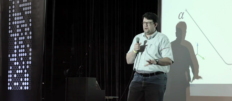
Derek Schulte’s discussion of path planning for 3D printers is fascinating because it shines a flashlight into that hidden middle layer. The slicer may generate G-code, but the printer cannot simply obey every line like a caffeinated plotter. Real machines have mass, belts, motors, flex, friction, acceleration limits, and tiny mechanical grudges. Path planning is the art of turning ideal instructions into motion a physical printer can actually perform.
In Schulte’s case, the subject becomes even more interesting because of his work with the New Matter MOD-t, a consumer 3D printer that took a different mechanical approach from many hobby machines of its era. Instead of the typical open-loop stepper setup found on many desktop printers, the MOD-t used closed-loop feedback and DC motors, paired with a more capable 32-bit ARM controller. That design choice made the firmware’s motion planning especially important. The printer had to know where it wanted to go, where it actually was, and how to get there without shaking itself like a washing machine full of bricks.
What Path Planning Means in 3D Printing
Path planning is the process of deciding how a printer’s toolhead should move through space over time. It is not just a question of “what line comes next?” It includes speed, acceleration, cornering behavior, extrusion timing, travel moves, temperature effects, and the limitations of the printer’s motion system.
In a typical FDM or FFF printer, the digital model is sliced into layers. Each layer becomes a set of perimeters, infill lines, top and bottom surfaces, support structures, and travel moves. The slicer converts this plan into G-code, a human-readable machine language that tells the printer where to move, how fast to move, and when to extrude. That sounds complete, but it is only the beginning of the story.
The printer firmware still has to execute those commands. It must decide how quickly to accelerate, how to slow down before corners, whether several short moves can be blended smoothly, and how to avoid pushing the machine beyond its physical limits. Without smart path planning, a printer would either crawl along painfully slowly or fling its toolhead around like it just discovered energy drinks.
Why Derek Schulte’s Talk Still Matters
Derek Schulte’s path-planning discussion remains relevant because it focuses on the gap between ideal G-code and real-world machine behavior. Many 3D printing beginners assume poor print quality is caused only by nozzle temperature, bed leveling, or filament quality. Those matter, of course. But the printer’s motion planner can be just as important.
Every corner is a negotiation. If the printer moves too fast into a sharp turn, the toolhead may overshoot, ringing may appear on the surface, or filament may pile up at the corner. If the printer slows too much, print time increases and extrusion pressure may cause blobs. A good motion planner balances speed and accuracy so the print looks clean without requiring the patience of a medieval monk.
Schulte’s perspective is especially useful because the MOD-t used closed-loop control. Most stepper-based printers assume that when the firmware commands a motor to move a certain number of steps, the printer actually moved that distance. In an open-loop system, the controller usually does not directly confirm position. If the motor skips steps, the printer may continue confidently in the wrong place, like a tourist following a map upside down.
Closed-loop systems add feedback. They can measure position and adjust motion accordingly. That opens the door to different motor choices and smarter correction, but it also makes planning more complex. The firmware must account not only for desired motion but also for measured response. In other words, path planning becomes less like reading sheet music and more like conducting an orchestra where the violin section occasionally texts back, “Actually, we are three millimeters behind.”
The Journey From Model to Motion
Step 1: The CAD Model
Everything starts with geometry. A designer creates a model in CAD software or downloads one from a repository. The model may look perfect on the screen, but the printer cannot directly print triangles and curves as abstract shapes. It needs instructions.
Step 2: The Slicer Builds the Toolpath
The slicer cuts the model into horizontal layers and calculates the toolpath. It chooses wall order, infill pattern, seam position, support placement, travel routes, retractions, extrusion widths, and layer heights. Modern slicers such as PrusaSlicer, Cura, OrcaSlicer, and Simplify3D give users huge control over these decisions.
This is where many visible print artifacts are born. A seam placed on the front of a decorative object may create a vertical scar. Excessive travel moves may cause stringing. Infill choices can influence strength and print time. Support paths can determine whether a model survives removal or leaves behind a surface that looks like it fought a raccoon.
Step 3: G-code Describes the Plan
G-code is the bridge between slicer and firmware. It contains movement commands, extrusion values, temperature settings, fan instructions, acceleration changes, and other machine behaviors. Commands such as movement, acceleration, and advanced motion settings tell the printer what to attempt, but they do not magically remove the limits of physics.
Step 4: Firmware Turns Commands Into Motion
The firmware’s motion planner reads upcoming G-code moves and decides how to execute them. Good firmware uses look-ahead planning, acceleration limits, junction deviation or jerk-style cornering rules, and step timing to produce smoother motion. The goal is not merely to follow the path, but to follow it at the best possible speed while maintaining quality.
Acceleration, Jerk, and Junctions: The Drama at Every Corner
Path planning becomes most visible at corners. A printer cannot instantly change direction. The toolhead has mass. Belts stretch. Frames flex. Motors have torque limits. If the firmware pretends otherwise, the result is ringing, layer shifts, rough corners, and angry forum posts typed at 1:17 a.m.
Acceleration controls how quickly the printer changes speed. Higher acceleration can reduce print time, but it increases mechanical stress and vibration. Lower acceleration improves smoothness but may turn a simple bracket into a feature-length film.
Jerk and junction deviation are ways firmware decides how aggressively the printer can move through direction changes. Older approaches often used “jerk” settings to define allowable instant speed changes. More modern approaches may use junction deviation, which aims to calculate cornering behavior based on path geometry and motion constraints. Either way, the firmware is asking the same practical question: how fast can we take this corner without making the print look like it was assembled during an earthquake?
Extrusion Is Part of Path Planning Too
Motion planning is not only about X, Y, and Z movement. The extruder is part of the dance. When the toolhead accelerates, slows, or turns, pressure inside the hot end changes. Filament does not behave like a perfect digital signal. It compresses, melts, oozes, drags, and occasionally expresses its feelings as a blob.
Features such as Linear Advance in Marlin and Pressure Advance in Klipper try to compensate for pressure changes in the nozzle. The idea is simple in concept: push filament earlier or later based on speed changes so that deposited material stays consistent. In practice, tuning it can feel like teaching toothpaste calculus.
When extrusion pressure is poorly controlled, corners may bulge, seams may form zits, and thin walls may look uneven. When it is tuned well, corners sharpen, surfaces become cleaner, and the printer behaves more like a precise manufacturing machine than a plastic glue gun on rails.
Closed-Loop Feedback and the MOD-t Difference
The MOD-t’s closed-loop design made Schulte’s path-planning topic particularly rich. Traditional stepper systems are popular because they are simple, reliable, and inexpensive. If the motor is sized properly and the printer is not pushed too hard, open-loop stepper control works very well. That is why so many desktop printers use it.
Closed-loop DC motor control changes the assumptions. Feedback allows the controller to monitor actual position and respond to errors. That can reduce the need for conservative safety margins and may enable different mechanical designs. But feedback is not magic pixie dust. It requires careful control algorithms, fast processing, stable firmware, and a motion planner that understands the machine’s dynamics.
This is the heart of Schulte’s insight: path planning is the interpreter between ideal geometry and real hardware. A slicer may say, “Go from point A to point B at this speed.” The planner must reply, “Lovely idea, but we have belts, motors, inertia, and a plastic noodle to manage.”
Modern Firmware: Marlin, Klipper, and the Motion Race
Today’s 3D printing firmware has become far more sophisticated. Marlin remains widely used and supports extensive motion settings, acceleration control, Linear Advance, input shaping features in some configurations, and broad compatibility across many machines. Klipper takes a different approach by offloading much of the motion calculation to a more powerful host computer, while the printer’s control board handles precise step generation.
Klipper’s input shaping is a strong example of modern path planning meeting vibration control. Ringing, also called ghosting, appears when the printer vibrates after sharp motion changes. Input shaping modifies motion commands to reduce excitation of those resonances. It is like telling the printer, “Please stop doing jazz hands after every corner.”
These advances show how path planning has moved from a hidden firmware detail into a mainstream performance topic. When users chase faster prints on CoreXY machines, tune accelerometers, adjust pressure advance, and compare slicer-generated paths, they are participating in the same conversation Schulte highlighted: how do we make the real machine match the digital intent?
Toolpath Planning Is Also About Strength
Print quality is not only cosmetic. Toolpath choices can change mechanical performance. Infill direction, perimeter order, layer bonding, seam placement, and travel interruptions all affect how a part handles load. Research in additive manufacturing has shown that toolpath strategies influence material usage, build time, thermal behavior, surface quality, and part strength.
For example, a bracket printed with poorly chosen infill orientation may fail sooner than one printed with paths aligned to expected stress. A thin decorative vase may benefit from continuous spiral motion. A functional part may need extra perimeters, slower outer walls, and a path that avoids weak seams in high-stress areas.
In industrial additive manufacturing, path planning becomes even more complex. Metal printing, continuous-fiber printing, multi-material printing, robotic extrusion, and non-planar printing all require careful path design. The path determines heat accumulation, residual stress, bonding quality, and dimensional accuracy. Desktop users see blobs and ringing; industrial users see scrap parts, failed certification, and engineers staring silently into coffee.
Why Slicers Cannot Solve Everything Alone
It is tempting to assume the slicer should generate perfect instructions and the printer should just obey. But slicers do not always know the exact mechanical condition of the printer. Belt tension, frame stiffness, motor current, nozzle pressure, filament behavior, resonance, and lubrication vary from machine to machine.
That is why path planning must be shared between slicer and firmware. The slicer chooses geometry and broad strategy. The firmware executes motion within machine limits. The user tunes the system. The printer contributes drama.
A slicer can reduce travel moves, hide seams, select efficient infill, and manage retraction. Firmware can smooth motion, enforce acceleration limits, compensate pressure, and reduce vibration. Hardware provides the boundaries. A great print happens when all three stop arguing.
Specific Example: Printing a Calibration Cube
Consider a simple 20 mm calibration cube. The model looks boring, but the motion planner sees a workout. Each layer has square perimeters, infill, starts, stops, direction changes, and extrusion pressure transitions. If acceleration is too high, the corners may ring. If pressure advance is poorly tuned, the edges may bulge. If jerk or junction settings are too aggressive, the toolhead may snap through corners and leave artifacts. If they are too conservative, the cube prints slowly and may show blobs where motion pauses.
Now scale that problem to a complex figurine with tiny fingers, overhangs, supports, internal infill, and curved surfaces. The planner must handle thousands of small segments while keeping motion smooth. This is why tiny G-code moves can challenge older 8-bit boards and why stronger processors or host-assisted firmware can improve performance.
What Makers Can Learn From Schulte’s Approach
The practical lesson is simple: print quality is not one setting. It is a system. When a print looks bad, do not only blame the filament. Look at the path. Is the seam in a bad location? Are travel moves crossing visible walls? Is the printer slowing sharply at corners? Are acceleration settings too ambitious? Is the extruder pressure lagging behind speed changes?
Schulte’s path-planning perspective encourages users to think like firmware engineers. The printer is not drawing a picture; it is managing time, force, heat, and material flow. Once you see that, troubleshooting becomes less mysterious. The weird blob on the corner is not a curse. It is evidence.
The Future of 3D Printer Path Planning
The future points toward smarter, more adaptive systems. Printers are already using accelerometers for resonance measurement, cameras for monitoring, load cells for probing, and increasingly powerful processors for motion calculation. Research is pushing toward optimized toolpaths for strength, thermal control, multi-material gradients, and non-planar surfaces.
Eventually, more printers may adjust paths in real time based on feedback. They may detect extrusion inconsistency, compensate for vibration, adapt to part geometry, and optimize strength automatically. In that world, path planning will become less like following a static recipe and more like a chef tasting the soup while cooking. Ideally, the chef will not be a robot with a nozzle full of PLA, but we should not limit innovation.
Experience Notes: What Path Planning Teaches You at the Workbench
After spending time around 3D printers, one lesson becomes painfully clear: the nozzle always tells the truth. You can set beautiful values in a slicer profile, name the file “final_final_really_final.gcode,” and feel like a manufacturing genius. Then the printer starts moving, and every hidden weakness in the path shows up on the part.
The first experience many users have with path planning is the mysterious seam. A model looks perfect in preview, but the printed object has a vertical line of bumps where each layer begins and ends. That is not random. It is the physical signature of start-stop motion, pressure changes, and seam placement. Move the seam to a corner, tune retraction, adjust pressure advance, or use spiral vase mode when appropriate, and the same machine suddenly looks smarter.
Another common lesson comes from speed. Everyone wants faster prints until the printer starts decorating the walls of a cube with ghostly echoes. Ringing is not just a cosmetic issue; it is a message from the frame. The motion path is exciting the printer’s natural vibration. Lower acceleration, tune input shaping, tighten the machine, and the echoes fade. The printer was not being rebellious. It was obeying physics too enthusiastically.
Travel moves teach another valuable lesson. A slicer preview may show blue non-printing moves hopping across open spaces. Those moves can save time, but they can also drag a little ooze across the surface. Combing, z-hop, retraction, travel speed, and path order all change the final result. Sometimes the fastest route is not the cleanest route. This is also true in airports, grocery stores, and conversations with toddlers.
Functional parts reveal the deeper value of toolpath planning. A hook, bracket, hinge, or drone mount may look fine but fail along a weak layer or seam. Changing wall count, infill direction, print orientation, and perimeter order can make the difference between a useful part and a sad little plastic apology. Path planning is not merely about where the nozzle goes; it is about how the finished object behaves.
Derek Schulte’s ideas are useful because they remind makers that the printer is a real machine, not a magic box. Every command has to pass through motors, belts, bearings, firmware, heat, and molten plastic. Better prints come from respecting that chain. Once you understand path planning, troubleshooting becomes more logical and more satisfying. You stop asking, “Why did my printer ruin this?” and start asking, “What did the path ask the machine to do?” That shift is powerful. It turns frustration into diagnosis, and diagnosis into better parts.
Conclusion
Derek Schulte’s “Path Planning For 3D Printers” remains a valuable lens for understanding why 3D printing is more than slicing a model and pressing start. Path planning sits at the intersection of software, firmware, mechanics, and material science. It decides how ideal geometry becomes physical motion, and how physical motion becomes a finished object.
From the New Matter MOD-t’s closed-loop design to today’s high-speed Klipper machines, the core challenge remains the same: a printer must translate G-code into smooth, accurate, reliable movement. Acceleration, jerk, junction deviation, extrusion pressure, feedback, vibration, and toolpath strategy all shape the result.
For makers, the takeaway is practical. If you want better prints, study the path. Watch the preview. Tune motion settings carefully. Respect the limits of your machine. Think about seams, travel moves, pressure, and vibration. The printer may be small enough to sit on a desk, but the planning problem inside it is wonderfully deep. Also, yes, it will still occasionally create plastic spaghetti. That is not failure; that is tradition.