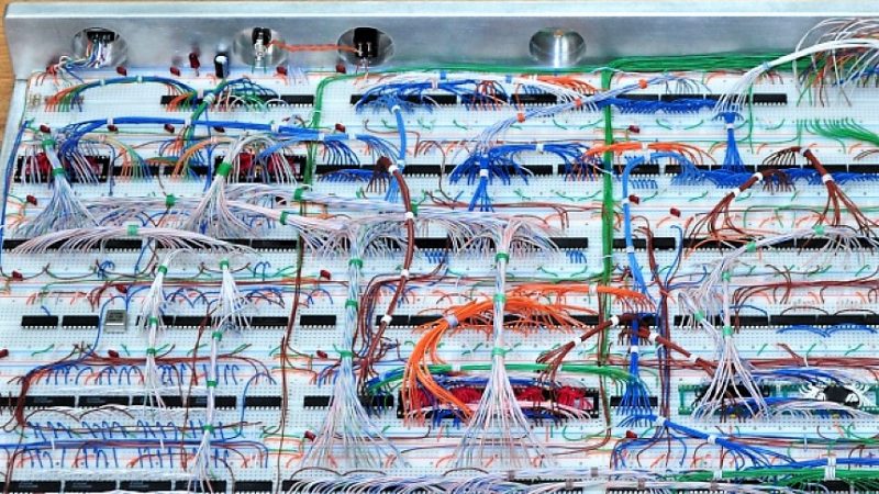
Building a 6502 computer on solderless breadboards is the kind of project that starts innocently (“I just want to blink an LED”)
and ends with you owning more jumper wire than socks. It’s retrocomputing with a plot twist: you’re not restoring a vintage machine
you’re becoming the vintage machine’s supply chain, manufacturing line, and quality-control department.
And yes, it can get hilariously big. One famous build philosophy is basically: “Pretend it’s 1979, limit yourself to the chips you
could’ve bought back then, and make it work anyway.” The result? Acres of breadboard, dozens of DIP packages, and the kind of wire
artistry that looks like a spaghetti bowl got a CS degree.
Why the 6502 Still Has People Building Computers Like It’s a Disco Night
The 6502 isn’t just an old microprocessor it’s a cultural artifact with a very practical hobbyist superpower: it’s simple enough to
understand at the “signals-on-a-table” level, but capable enough to run real software (monitors, games, even BASIC) once you give it
memory and I/O.
A quick “what makes it special” breakdown
- 8-bit data bus + 16-bit address bus = it can directly address 64 KB of memory space (a whole universe in 1979 terms).
- Small, elegant programmer’s model (A, X, Y, stack pointer, status flags) that’s friendly to learning assembly.
- Huge community and documentation footprint, plus modern CMOS descendants (like W65C02) that are easier to use today.
Historically, 6502-family chips powered landmark early personal computers and game systems. For today’s builder, that means you’re not
learning on an arbitrary CPU you’re learning on a piece of history that still rewards you with “I understand how computers really work”
moments.
“Acres of Breadboard”: The Big, Bold, 1979-Style Approach
Let’s talk about the headline idea: a 6502 computer built with dozens of chips and multiple solderless breadboards,
intentionally constrained to “parts you could plausibly have used before 1980.” That’s not just a flex it forces design decisions that
old-school engineers had to make: glue logic instead of programmable logic, careful memory mapping, and timing discipline if you want video.
One notable example of this style is a breadboard-based 6502 machine designed like it’s 1979, built across dozens of breadboards,
aiming for classic-era features like NTSC video output and multi-channel 8-bit sound. The “no PCB” rule adds
a delicious layer of chaos: you are building a computer out of friction-fit metal springs and optimism.
Why builders choose the “big breadboard” route
- Visibility: You can probe almost any signal. Every bus line is right there, begging to be understood.
- Modularity: You can treat sections like LEGO: CPU board, memory board, I/O board, video board, audio board.
- Authenticity: Glue logic makes you appreciate how much “software-defined everything” we take for granted now.
The Core Architecture: What a 6502 Computer Actually Needs
A bare CPU is just a very eager thinker with nowhere to put its thoughts. To become a computer, a 6502 system needs a few non-negotiables:
a clock, reset logic, memory (RAM + ROM), and some way to do input/output.
Minimum viable 6502 computer: the “it lives!” checklist
- CPU: 6502 or a modern compatible part like a W65C02.
- Clock: a stable signal (often a can oscillator or a simple clock circuit) to drive the CPU.
- Reset circuit: ensures the CPU starts cleanly and reads the proper reset vector.
- ROM: holds your firmware (monitor program, test code, or BASIC).
- RAM: where programs run and variables live.
- Address decoding: logic that decides which chip responds to which address range.
- I/O: a VIA (like the 65C22) or similar device so your computer can blink, beep, and talk.
The most important “invisible” design decision: the memory map
The 6502 sees a single 64 KB address space. Your job is to carve that space into regions RAM here, ROM there, I/O somewhere else
and then build decoding logic so only the correct chip answers for each address.
A classic beginner-friendly map might look like this:
That “vectors at the top” detail matters because a 6502 starts by reading fixed addresses near the top of memory to find where your reset
code lives. It’s one of the reasons ROM is commonly mapped to the high end of the address space.
The Chip Cast: RAM, ROM, VIA, and the Supporting Actors
Most hobbyist 6502 builds today use readily available memory chips and a VIA for I/O. A popular combination is:
62256 SRAM (32 KB) + 28C256 EEPROM (32 KB) + W65C22 VIA.
That trio gives you enough room for a monitor program plus real experiments timers, interrupts, and ports you can connect to displays
and keyboards.
Why the VIA is a superstar
The VIA is like giving your CPU hands, a stopwatch, and a doorbell. With it, you can:
- Read buttons and keyboards
- Drive LEDs, LCDs, and simple displays
- Use timers for sound generation or scheduling
- Trigger interrupts so your computer can react instead of constantly polling
In big breadboard builds, a VIA (or several) becomes the glue between “CPU thinks” and “system behaves.”
Address Decoding: The Bouncer at the Memory Club
Address decoding is the art of looking at the address bus and saying: “You! ROM. You! RAM. You! That I/O chip that always wants attention.”
Do it wrong and two chips may try to drive the data bus at once, which is the electronic equivalent of two people grabbing the same microphone
and screaming different karaoke lyrics.
A practical decoding approach with classic logic
A common method uses a decoder chip (like a 74xx138) to break the 64 KB space into chunks, then uses additional gates to refine chip-selects.
On breadboards, simpler is often better fewer chips means fewer wires, and fewer wires means fewer opportunities for your build to become
an abstract sculpture.
A “good enough and easy to debug” strategy is:
- Use high address lines (A15, A14, A13…) to select regions.
- Map ROM high so reset vectors are guaranteed to be in ROM.
- Give I/O a small, clearly defined window (even 16–256 bytes is plenty to start).
Many builders also gate selects with the CPU clock phase used for valid bus cycles. This can reduce accidental bus contention and weird
“it works until I touch the wire” behavior.
Clock and Reset: The Two Signals That Decide Whether You Have a Computer or Modern Art
A 6502-family system lives and dies by two things: a clean clock edge and a sane reset sequence. If either is flaky, you’ll get symptoms
like random opcodes, phantom writes, or the classic breadboard phenomenon: “It runs perfectly until I look at it.”
Clock tips that keep you out of trouble
- Start slow. A few hundred kHz (or even manual single-step) can make debugging dramatically easier.
- Keep the clock wire short. Long clock lines on breadboards can ring and double-trigger.
- Buffer if needed. If many chips depend on the clock, a buffer/driver can help keep edges crisp.
Reset done right
Reset circuitry typically holds the CPU in reset long enough for power to stabilize, then releases cleanly. A sloppy reset can put the CPU
into an undefined state which is a polite way of saying “it will do nonsense at high speed.”
NTSC Video and Multi-Channel Sound: When Your Breadboard Wants to Become a TV Station
The jump from “CPU + RAM + ROM” to “video output” is where projects earn the “acres of breadboard” label. Video means timing.
Timing means counters, shift registers, comparators, and a lot of glue logic. It’s not that the 6502 can’t handle video it’s that
generating a stable analog video signal pushes you into hardware that must behave consistently down to microseconds.
What “NTSC video output” usually implies
- Sync generation: horizontal and vertical sync pulses at the right cadence
- Pixel timing: a predictable “dot clock” for when pixels change
- Video memory or registers: a way to turn bytes into visible patterns
- Analog output shaping: resistors (and sometimes transistors) to get usable voltage levels
Add 4 channels of 8-bit sound and you’re basically building a tiny synthesizer too. That often means DACs (or resistor ladder
networks), timers, mixing, and careful grounding so your video doesn’t pick up the musical stylings of your address bus.
Power and Signal Integrity on Breadboards: Where Most Builds Go to “Character Development”
Breadboards are fantastic learning tools and also tiny obstacle courses for high-speed digital signals. The issue is not that breadboards
are “bad,” it’s that they have parasitics and long return paths that you must respect, especially with fast logic families.
Decoupling capacitors aren’t optional they’re the entrance fee
Digital chips gulp current in short bursts when they switch. Without nearby decoupling capacitors, those gulps cause little voltage dips and
spikes on the power rails. On a big breadboard computer, that becomes a recipe for random crashes and “ghost bugs.”
- Local decoupling: a small capacitor (often 0.1 µF) placed close to each chip’s power pins.
- Bulk decoupling: a larger capacitor near where power enters a board section to stabilize the rail.
- Short loops: keep the capacitor-to-chip wiring short to minimize inductance.
Other breadboard survival practices
- Power distribution like you mean it: don’t rely on one skinny rail for an entire multi-board system.
- Ground is a signal too: return paths matter; big loop areas invite noise.
- Slow down first, speed up later: a stable slow computer beats a fast haunted one.
- Label everything: the human brain has limited GPIO.
Debugging Like a 1979 Engineer (With 2026 Tools)
The most effective breadboard builds are the ones designed for debugging from day one. You can absolutely use modern helpers without breaking
the retro vibe think of it as “period-accurate computer, modern therapist.”
Debug moves that save hours
- Single-step clock: manually pulse the clock to watch fetch cycles happen.
- Bus monitoring: LEDs on key lines, or a microcontroller-based monitor to log addresses/data.
- Known-good test ROM: start with a tiny program that toggles a pin so you can prove the system is alive.
- Incremental expansion: CPU → RAM/ROM → decoding → VIA → video/sound, not all at once.
One practical milestone is getting a monitor program running: something that prints a prompt over serial, lets you inspect memory, and load
small programs. Another classic milestone is BASIC because nothing says “computer” like typing
10 PRINT "HELLO" and feeling 47 years younger.
Software on a Homebrew 6502: From Blinking LEDs to BASIC
Once the hardware is stable, software becomes the fun part (and also the part where you realize you are now the operating system).
Most builders follow a progression like:
- Smoke tests: tiny programs to verify RAM, ROM, and I/O.
- A monitor: read/write memory, jump to addresses, maybe upload over serial.
- Games and demos: because joy is a valid engineering requirement.
- BASIC or a higher-level environment: for faster iteration and “real computer” vibes.
Conveniently, the 6502 ecosystem has a long tradition of BASIC interpreters, and recent preservation work has made historical source code
easier to explore and learn from. Even if you don’t run a full BASIC, borrowing concepts from classic monitors and development kits can
accelerate your project.
When “Acres of Breadboard” Wants to Graduate to a PCB
Breadboards are unbeatable for discovery but large systems eventually hit limits: mechanical fragility, wiring density, and the sheer
probability that one loose connection will ruin your evening. Many builders prototype on breadboards, then migrate to perfboard or a custom
PCB once the design is proven.
The best time to consider a PCB isn’t when you’re tired it’s when you have a stable, well-understood schematic and a memory map you love.
In other words: after you’ve wrangled the spaghetti into something that behaves like a computer.
Conclusion
A 6502 breadboard computer is equal parts engineering, archaeology, and comedy. It teaches you how timing, memory maps, and signal integrity
actually shape a machine not in theory, but in the “why did my program counter jump into the sun?” reality of physical electronics.
Whether you’re building a compact educational 6502 system or a full “1979-style” monster with NTSC video and multi-channel sound, the lesson
is the same: computers are understandable. They’re just picky. Give the bus clean signals, give the chips good power, and give yourself
permission to debug one wire at a time.
Build Experiences: What It’s Like to Create a 6502 Breadboard Computer (500+ Words)
People who build breadboard 6502 computers often describe the experience as a roller coaster that starts with confidence and ends with deep
respect for decoupling capacitors. The first “experience milestone” is usually the moment your CPU does something undeniably intentional
an LED toggles, a pin pulses, or your monitor prints a character. It feels small, but it’s not. You’ve just watched a real processor fetch
instructions from real memory you wired by hand. That moment has a weird kind of magic: the system is no longer a pile of parts, it’s a
tiny, obedient universe.
The second milestone is also unforgettable: the first time it almost works. Maybe it boots once every five resets, or it runs
perfectly until you add one more wire. Builders learn fast that breadboards reward tidy layout and punish “close enough” wiring. It’s common
to spend an hour chasing a bug that turns out to be a swapped power rail, a split breadboard bus, or a single jumper that’s off by one hole
the electronic equivalent of misplacing your house key by half a millimeter.
As the system grows, the build becomes less like “wiring a circuit” and more like “organizing a small city.” You’ll start grouping your
wiring by function: address bus lines bundled and routed consistently, data bus lines kept short, control lines labeled. Many builders end
up creating their own rituals: color-coding jumpers, printing tiny labels, or keeping a notebook of “what changed since it last worked.”
That last one is not optional it’s your future self’s emergency hotline.
Then comes the phase where you discover the emotional spectrum of clocks. A slow single-step clock makes you feel like a genius because
you can watch each instruction happen. A fast clock makes you feel like you’re holding a live animal because everything becomes sensitive:
wire length matters, grounding matters, and suddenly the build has moods. The most common “breadboard computer epiphany” is realizing that
power and ground are not background characters they are main characters with speaking lines. Adding one more 0.1 µF capacitor can feel
like solving a mystery with a single dramatic clue.
If you chase video output (especially NTSC-style signals), the experience changes again. Builders often report that video brings a new kind
of discipline: timing has to be consistent, and sloppy wiring gets caught instantly by a display that refuses to lock onto sync. Debugging
becomes half electrical (clean edges, stable rails) and half conceptual (when should pixels be read? how do counters align with scanlines?).
It can be frustrating and also intensely satisfying because every improvement is visible. When your screen goes from “rolling nonsense”
to a stable image, it’s like watching your computer learn to speak clearly.
The final “experience milestone” is software confidence. Once you can reliably boot into a monitor or run a BASIC prompt, you stop feeling
like you’re babysitting hardware and start feeling like you’re using a computer you created. That’s the point where people write little
games, play with sound routines, or build tools to upload code faster. The project becomes creative instead of purely corrective. You still
debug, of course but now it’s in service of making something fun, not just making something boot.
And that’s the lasting experience people take away: building a 6502 breadboard computer doesn’t just teach electronics or assembly language.
It teaches patience, method, and the rare joy of understanding a machine all the way down to its wires. Also, it teaches you to buy jumper
wires in bulk because you will, without question, need “just one more.”