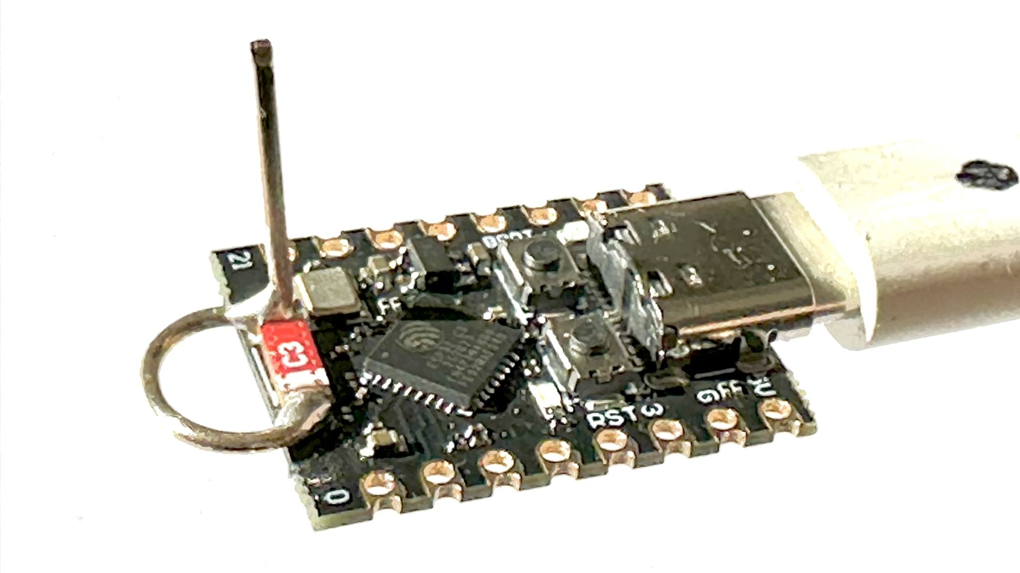
The ESP32-C3 is one of those tiny boards that makes makers behave dangerously optimistic. It has WiFi, Bluetooth LE, a RISC-V core, low power features, and enough GPIO to convince you that your next “quick weekend project” will definitely not become a three-week debugging opera. Yet many people discover the same annoying truth after flashing their first sketch: the code works, the router works, the coffee works, but the WiFi range feels like it was negotiated by a houseplant.
That is where a simple antenna modification enters the story. A basic wire antenna added to certain ESP32-C3 SuperMini-style boards can dramatically improve WiFi signal strength, stability, and usable range. The mod is not magical. It is radio-frequency physics wearing a tiny solder joint. But for hobbyists, sensor builders, and anyone trying to keep a small IoT device connected from across the room, garage, garden, or “why is the router in the worst possible location?” basement, the improvement can feel magical.
This article explains why the stock antenna on some compact ESP32-C3 boards struggles, how a simple wire antenna can help, what the reported results mean, and what you should consider before heating up the soldering iron like a tiny RF blacksmith.
What Is the ESP32-C3, and Why Is Everyone Using It?
The ESP32-C3 is a low-power microcontroller from Espressif built around a single-core 32-bit RISC-V processor. It supports 2.4 GHz WiFi using 802.11 b/g/n and Bluetooth 5 Low Energy, making it a popular choice for smart home sensors, automation gadgets, wireless buttons, LED controllers, environmental monitors, and other Internet of Things projects.
Compared with older ESP8266 boards, the ESP32-C3 offers a more modern architecture, better security features, Bluetooth LE support, and a friendly development ecosystem. It is also available in tiny development boards that cost very little. That combination is irresistible. Makers see a board smaller than a stick of gum and immediately think, “Yes, this should monitor my mailbox, water my plants, and maybe control the lights in my kitchen.”
The catch is that wireless performance is not controlled by the chip alone. Firmware matters. Power supply matters. Router placement matters. But the antenna matters enormously. A brilliant WiFi chip connected to a poor antenna is like giving a world-class singer a pillow and asking for a concert.
Why Some ESP32-C3 Boards Have Weak WiFi
Many ESP32-C3 SuperMini boards are designed to be as small and cheap as possible. That is great for breadboards, compact projects, and impulse purchases at midnight. However, antennas do not love being squeezed into corners, surrounded by copper, trapped near USB connectors, or placed too close to ground planes and components.
Several small ESP32-C3 boards use a compact ceramic chip antenna, often mounted at the end of the PCB. Ceramic antennas save space, but they are sensitive to layout. They usually require a proper ground plane, a keep-out area, careful feed design, and sometimes a matching network to perform well. When a board is extremely cramped, the antenna may be physically present but electrically unhappy. And an unhappy antenna does not politely file a complaint; it simply gives you weak RSSI, packet retries, random disconnects, and the emotional journey known as “but it worked on my desk yesterday.”
Espressif’s own RF design guidance emphasizes the importance of antenna matching, PCB layout, ground planes, and proper antenna selection. In a polished commercial product, these details are tested with RF tools such as a vector network analyzer, calibrated measurement setups, and real enclosure testing. In the ultra-cheap dev board universe, the design goal is often closer to “make it small, make it boot, and please let the USB-C connector stay attached.”
The Simple Antenna Mod: A Small Wire With Big Results
The antenna modification that attracted attention in the ESP32-C3 community is refreshingly simple. The basic version uses a short piece of wire, around 31 mm long, formed into a loop at one end and soldered across the existing ceramic antenna terminals. The loop can be shaped around a small drill bit, then opened slightly so it bridges the original SMD antenna. The remaining section sticks upward, giving the radio a freer-standing radiating element.
Why around 31 mm? At 2.4 GHz, a quarter wavelength in free space is roughly 31 mm. Real antennas are affected by wire diameter, nearby materials, board layout, solder joints, and the surrounding environment, so the perfect length is not always exactly 31 mm. Some experimenters reported strong results with slightly different lengths, including around 34 mm for certain boards and orientations. The important idea is not that 31 mm is a holy number carved into the copper tablets of WiFi destiny. It is a practical starting point for a quarter-wave-style radiator near the 2.4 GHz band.
Reported improvements from the mod are impressive. Tests using RSSI logging showed gains around 6 to 10 dB on some ESP32-C3 SuperMini boards, with other experiments reporting even larger improvements depending on the antenna shape and setup. In plain English, that can mean a board that previously struggled to connect may become stable in the same location. A device that only worked near the router may suddenly behave like it remembers it is supposed to be wireless.
Understanding RSSI Without Needing a PhD in Radio
RSSI stands for Received Signal Strength Indicator. It is a measurement of how strongly a device hears a WiFi signal. In many ESP32 projects, RSSI is shown in dBm as a negative number. For example, -45 dBm is stronger than -70 dBm. This is one of those engineering conventions that makes perfect sense after you stare at it long enough and slightly question your life choices.
A 6 dB improvement is meaningful. A 10 dB improvement is very meaningful. Since the decibel scale is logarithmic, small-looking numbers can represent large changes in received signal power. However, RSSI is not the entire story. Better RSSI usually helps with reliability, but real WiFi performance also depends on noise, interference, router quality, channel congestion, walls, device orientation, and power supply stability.
Think of RSSI as the volume of a person speaking across a crowded room. Turning up the volume helps, but if ten blenders are running between you and the speaker, conversation may still be messy. In WiFi terms, those blenders are neighboring routers, microwave ovens, Bluetooth devices, metal enclosures, bad cables, and the mysterious RF behavior of your refrigerator.
Why the Wire Antenna Works
The wire antenna helps because it gives the ESP32-C3 radio a more effective structure for radiating and receiving energy in the 2.4 GHz band. A tiny ceramic chip antenna can work well when placed according to its datasheet, but if the board layout compromises its required clearance or ground reference, performance drops. The wire mod moves part of the radiating structure into open air, where it is less smothered by the board.
In simple terms, the antenna finally gets breathing room. The original antenna may be electrically detuned by nearby components and lack of keep-out space. By adding a wire element, the system changes the effective antenna geometry and can improve coupling to the surrounding space. It is not a precision laboratory redesign, but it can be a practical hack that works surprisingly well on boards with poor stock antenna layouts.
There is an important distinction here: this mod is not guaranteed to improve every ESP32-C3 board. If your board already has a well-designed PCB antenna or a proper external antenna connector, a random wire may do little or even make things worse. Antennas are picky creatures. They are basically cats made of impedance.
When This ESP32-C3 Antenna Hack Makes Sense
This modification makes the most sense when you are using a tiny ESP32-C3 SuperMini-style board with weak WiFi, especially one with a small ceramic antenna and very little open space around it. It is useful for hobby projects, prototypes, test fixtures, and indoor IoT devices where reliability matters more than a perfect professional appearance.
Good candidates include temperature sensors in another room, garage door monitors, plant watering controllers, wireless LED projects, battery-powered loggers, and small web-server experiments. If the board connects only when it feels emotionally supported by the router, an antenna improvement may help.
However, this hack is less ideal for sealed commercial products, certified devices, ultra-compact builds, or projects that must fit inside a tight enclosure. Once you modify an antenna, you may affect regulatory compliance, radiation pattern, and repeatability. For products intended for sale, it is better to use certified modules, follow manufacturer layout guidance, and test the final enclosure properly.
How to Approach the Mod Safely and Sensibly
The basic concept is simple, but the work is small and delicate. The antenna pads on tiny boards are not designed for heroic soldering battles. Use a fine-tip soldering iron, good lighting, flux, tweezers, and patience. If you are new to soldering, practice on scrap electronics first. The goal is to attach the wire cleanly, not to roast the ceramic antenna like a marshmallow at a campfire.
Keep the added wire away from metal cases, batteries, USB cables, and large copper areas as much as possible. Orientation matters. A vertical element may perform differently from one folded sideways. A coiled wire may save space, but coiling can change inductance and detune the antenna. That is why some tests found that compacting the antenna reduced the benefit.
After the mod, test before celebrating. Use a simple RSSI logger or repeated WiFi scans from the same location. Compare the unmodified and modified board if you have two units. Keep the router, board position, power supply, and test distance consistent. Otherwise, you may end up measuring your own movement, your laptop lid angle, or the fact that someone closed a door.
Testing ESP32-C3 WiFi Performance the Right Way
A useful test does not need to be complicated. Flash a sketch that connects to your WiFi network and prints RSSI every few seconds. Place the board in one location and record values for a minute or two. Then repeat after the antenna modification. Better yet, test in several locations: near the router, one room away, behind a wall, near the edge of reliable coverage, and inside the intended enclosure.
Look for more than the highest number. Stable RSSI matters. Fewer disconnects matter. Faster reconnects matter. If the signal improves from -78 dBm to -68 dBm and the device stops dropping offline, that is a practical win. If the signal jumps around wildly, the antenna may be too sensitive to orientation or nearby objects.
You can also test real application behavior. Does your MQTT sensor publish reliably? Does the web server load faster? Does OTA firmware updating work from the device’s final location? Does the board survive overnight without disappearing from the network like a magician with commitment issues? These real-world tests often matter more than a pretty RSSI graph.
Simple Antenna vs. External Antenna Connector
If you want the cleanest solution, choose an ESP32-C3 module or board with a proper external antenna connector. Espressif offers module variants with onboard antennas and variants designed for external antennas. A U.FL, IPEX, or similar connector lets you use a tested 2.4 GHz antenna without improvising directly across a tiny ceramic part.
That said, external antenna boards may cost more, take more space, and require the correct pigtail or antenna. Some boards also need a jumper or component change to select the external antenna path. Always check the board documentation before assuming the connector is active. A connector that is not properly routed is just a decorative RF belly button.
The simple wire mod wins on cost and speed. It can rescue boards you already own. The external antenna wins on repeatability, mechanical strength, and professionalism. For a quick prototype, the wire hack is charming. For a product, use the proper RF path.
Design Lessons for Makers and PCB Builders
The bigger lesson is that wireless design is physical design. Software developers can pretend that radio waves are just invisible JSON, but the antenna disagrees. At 2.4 GHz, millimeters matter. Ground planes matter. Plastic enclosures matter. Human hands matter. Even the way a cable hangs from a board can change the result.
If you are designing your own ESP32-C3 PCB, follow Espressif’s hardware design guidelines closely. Include the recommended RF matching network. Preserve antenna keep-out areas. Avoid copper under antenna regions when the reference design says to avoid it. Copy proven reference layouts rather than inventing a new antenna shape during a lunch break. Antenna design is one of those fields where creativity is wonderful after measurement equipment enters the room.
For most makers, the practical takeaway is simple: if WiFi range is important, do not choose a board based only on size and price. Look at the antenna. A slightly larger ESP32-C3 board with a better PCB antenna may outperform a tiny board that looks adorable but whispers into the void.
Common Mistakes to Avoid
Using Any Random Wire Length
A random wire may improve things, but starting near a quarter wavelength for 2.4 GHz is smarter. Around 31 mm is a practical baseline. Trim and test only if you can measure consistently.
Putting the Board in a Metal Box
Metal enclosures block and reshape radio signals. If you must use metal, consider an external antenna mounted outside the enclosure.
Assuming RSSI Equals Internet Speed
Better RSSI helps, but throughput also depends on router settings, interference, WiFi mode, firmware, power supply quality, and network congestion.
Ignoring Power Supply Problems
Weak power can look like weak WiFi. If the ESP32-C3 browns out or sags during transmit bursts, an antenna will not fix the root problem.
Copying the Hack Into a Commercial Product
A hand-soldered antenna is fun for experiments, but commercial wireless products need proper testing, repeatable manufacturing, and regulatory compliance.
Real-World Example: A Sensor at the Edge of Coverage
Imagine an ESP32-C3 temperature sensor placed in a garage. On the desk near the router, it reports data perfectly. In the garage, it connects at boot, publishes two readings, then vanishes. The serial monitor shows weak RSSI, reconnect attempts, and occasional timeouts. Naturally, the first instinct is to blame the firmware, the router, the library, the moon, and possibly the neighbor’s smart toaster.
After adding a simple wire antenna and retesting from the same spot, the board may show a stronger and steadier RSSI. The MQTT messages arrive consistently. OTA updates no longer fail halfway through. The project changes from “science fair ghost story” to “working IoT node.” That is the kind of practical difference antenna performance can make.
Extra Experience: What Working With ESP32-C3 Antennas Teaches You
One of the most useful experiences with the ESP32-C3 is realizing that wireless projects are never just wireless in theory. They are wireless in your actual room, with your actual walls, router, cables, shelves, pipes, appliances, and questionable furniture placement. A board that behaves perfectly on a workbench can become moody when moved three meters away. This is not because the ESP32-C3 is bad. It is because radio waves interact with the environment in ways that are both predictable and deeply annoying.
When testing a simple antenna mod, the first lesson is consistency. Place the board in the same position every time. Do not hold it in your hand for one test and leave it on a wooden table for the next. Your body affects the antenna. The USB cable can affect the antenna. Even rotating the board can change the RSSI. If you want useful results, make the test boring. Boring tests are beautiful. Exciting tests are how you accidentally prove that walking across the room improves WiFi.
The second lesson is that the best improvement is not always the biggest number. A dramatic RSSI jump looks great, but stable connectivity is the real prize. For an IoT sensor, a steady -67 dBm connection may be better than a wildly swinging signal that occasionally peaks at -58 dBm. Your project does not care about bragging rights. It cares about sending the humidity reading before the plant becomes a botanical raisin.
The third lesson is mechanical durability. A bare wire antenna sticking out of a tiny board is wonderfully effective until it catches on a sleeve, bends into a battery, or gets crushed inside an enclosure. After the first successful test, think about strain relief and placement. A tiny dab of non-conductive support material, careful enclosure design, or simply positioning the board away from moving parts can prevent future sadness.
The fourth lesson is that antenna tuning is a rabbit hole with excellent acoustics. You can test 31 mm, 32 mm, 34 mm, straight wire, looped wire, angled wire, and wire that looks like modern art. Some changes will help. Some will do nothing. Some will make the signal worse while looking more impressive. This is why RF engineers measure instead of guessing. For hobby work, repeatable RSSI tests are a reasonable starting point, but they are not the same as professional antenna characterization.
The fifth lesson is board selection. After trying an antenna fix, many makers become more careful buyers. They start noticing whether a board has a real antenna keep-out area, whether it uses a module with a tested antenna, whether an external antenna connector is available, and whether the layout looks like someone respected RF design rather than challenged it to a duel. That awareness saves time on future projects.
Finally, the ESP32-C3 antenna experience teaches humility. You can write clean code, choose the right libraries, and build a neat enclosure, but a tiny piece of copper or ceramic can still decide whether the project works reliably. The simple wire antenna mod is popular because it reveals something powerful: sometimes the difference between flaky and dependable is not a new router, not a firmware rewrite, and not a dramatic rebuild. Sometimes it is 31 mm of wire, two careful solder joints, and the patience to test like you mean it.
Conclusion
A simple antenna can make a major difference for ESP32-C3 WiFi performance, especially on very small boards with cramped ceramic antenna layouts. The widely discussed ESP32-C3 SuperMini wire antenna mod shows how a short quarter-wave-style radiator can improve RSSI, range, and connection stability without replacing the entire board. It is inexpensive, educational, and surprisingly effective when used on the right hardware.
Still, this is a hack, not a universal law of radio. Results vary by board design, wire shape, enclosure, router, orientation, and environment. For hobby projects, it can be a brilliant fix. For commercial designs, proper modules, reference layouts, antenna matching, and compliance testing remain the grown-up path. In other words: use the simple antenna when your prototype needs help, but respect RF design when your product needs to behave.