Depositing metal on glass with a fiber laser sounds like the kind of project that belongs in a secret laboratory, preferably one with dramatic lighting and a scientist shouting, “Increase the power!” In reality, the basic idea can be surprisingly simple: place metal close to glass, focus laser energy into the metal, and use the resulting heat, ablation, molten droplets, or transfer effect to leave a metallic layer on the glass surface.
The process sits at the crossroads of laser marking, laser-induced forward transfer, glass metallization, thin-film experimentation, and good old-fashioned workshop curiosity. It is not the same as traditional vacuum sputtering or chemical vapor deposition. It is also not exactly the same as engraving glass. Instead, it uses a laseroften a near-infrared fiber laser around the 1064 nm rangeto interact strongly with metal while the glass acts as a nearby receiving surface.
For makers, researchers, and engineers, that is exciting. Glass is smooth, insulating, chemically stable, and transparent. Metal is conductive, reflective, and useful for circuits, electrodes, heaters, sensors, decorative marks, and optical effects. Getting metal to stick to glass without masks, furnaces, plating tanks, or vacuum chambers is a tempting shortcut. Like most shortcuts, it can be brilliant, messy, or both.
What Does “Depositing Metal On Glass With Fiber Laser” Mean?
In simple terms, metal deposition means creating a metal layer, trace, dot, coating, or pattern on a glass surface. With a fiber laser, this may happen through several related mechanisms. A thin foil or shim can be placed against the glass and struck with laser pulses. The laser energy melts or ejects tiny metal particles, which land on the glass and form a thin coating. In other approaches, metal powders, nanoparticle inks, or pre-coated donor films are transferred onto glass by laser heating.
The phrase can describe a workshop-scale experiment or a highly controlled microfabrication method. On the DIY side, a maker may sandwich copper, aluminum, brass, or stainless steel foil between glass plates and scan the laser across the metal. On the research side, scientists may use laser-induced forward transfer, laser-induced reverse transfer, laser micro-cladding, or laser-induced plasma deposition to create conductive patterns with carefully measured resistance and adhesion.
Why Fiber Lasers Are Useful for This Process
Fiber lasers are popular because they are compact, efficient, precise, and excellent at processing metals. A typical pulsed fiber marking laser can engrave, anneal, texture, and mark stainless steel, aluminum, copper, titanium, and many other materials. The beam can be focused into a small spot, moved quickly with galvanometer mirrors, and controlled through software. That makes it ideal for drawing patterns without a physical mask.
Glass, however, complicates the story. Clear soda-lime or borosilicate glass does not absorb a 1064 nm fiber laser beam as strongly as many metals do. That is why a fiber laser may pass through or weakly affect clear glass while rapidly heating the metal behind or against it. In the right arrangement, that weakness becomes useful: the glass can serve as a transparent window while the laser energy is absorbed by the metal donor.
How the Fiber Laser Metal-on-Glass Method Works
1. The Foil Sandwich Method
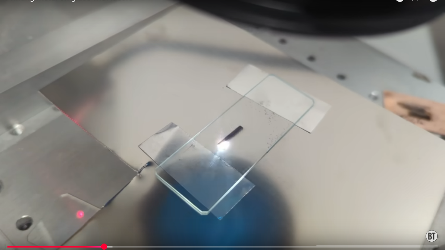
One practical method uses a piece of thin metal foil or shim stock sandwiched between two glass plates. The laser is focused on the metal. When the beam hits the metal, it creates intense localized heating. Small areas melt, vaporize, or eject microscopic droplets. Some of that material transfers to the adjacent glass surface.
Under magnification, the deposited layer often appears less like a smooth mirror film and more like a landscape of tiny splashes. Think of it as metallic drizzle at the microscale. It may look continuous from a distance, but the structure can be granular, uneven, porous, or dotted depending on laser power, speed, focus, pulse duration, and the metal used.
2. Laser-Induced Forward Transfer
Laser-induced forward transfer, often shortened to LIFT, uses a donor material placed near a receiving substrate. The laser pulse releases or propels material from the donor toward the receiver. In metal-on-glass work, the donor can be a thin metal film, metal nanoparticle ink, or metal-coated carrier. LIFT is attractive because it is maskless, digitally controlled, and capable of printing fine features.
In controlled systems, LIFT can deposit silver nanoparticles, conductive inks, or other functional materials. It has been studied for flexible electronics, black metal absorbers, sensors, and microelectronic interconnects. The basic idea is elegant: instead of carving away material, the laser helps place material exactly where it is needed.
3. Laser-Induced Reverse Transfer and Backwriting
Another family of techniques transfers metal toward the side from which the laser arrives or onto a nearby glass surface through a backwriting process. Researchers have used laser-induced scanning transfer deposition to form silver electrodes on glass. This approach can produce conductive coatings without vacuum equipment or liquid chemical baths, which makes it attractive for scalable and greener manufacturing concepts.
4. Laser Micro-Cladding With Metallic Pastes
Laser micro-cladding uses a paste containing metal particles, binders, and organic medium. The paste is applied to the glass, and the laser traces the desired circuit or electrode path. The laser sinters or bonds the metal-containing region, and the unprocessed paste can be removed afterward. This is more controlled than splashing metal from foil, though it requires formulated materials and post-processing.
Best Metals for Laser Deposition on Glass
Not all metals behave politely under a fiber laser. Some absorb well, some reflect stubbornly, some oxidize quickly, and some turn the experiment into a tiny fireworks audition. Common choices include copper, silver, aluminum, stainless steel, nickel, titanium, and brass. Each has trade-offs.
Copper
Copper is attractive because it is highly conductive and useful for circuit traces, antennas, heaters, and electrodes. The challenge is that copper reflects near-infrared laser light strongly, so it may require higher peak power, careful focusing, slower scan speeds, or surface preparation. Oxidation can also affect color and conductivity.
Silver
Silver is one of the best conductors and is widely used in printed electronics research. Silver nanoparticle inks and silver coatings can form useful conductive paths. The downside is cost. Silver is wonderful until your budget sees the invoice and quietly leaves the room.
Aluminum
Aluminum is lightweight, inexpensive, and easy to find as foil. It can transfer to glass, but its oxide layer forms quickly and may influence adhesion and electrical behavior. Aluminum deposits may be useful for experiments, decorative effects, optical scattering, or rough conductive areas.
Stainless Steel and Nickel
Stainless steel and nickel-based materials can be more forgiving under some fiber laser settings. They absorb better than copper and can create dark, durable marks or textured coatings. They may be useful where corrosion resistance or mechanical toughness matters more than maximum conductivity.
Brass and Other Alloys
Alloys are tricky because laser heating can separate elements with different melting points, vapor pressures, and oxidation behavior. Brass, for example, contains copper and zinc. Under intense heating, the deposit may not match the original alloy composition. The result can be beautiful, unpredictable, or scientifically annoyingsometimes all three before lunch.
Key Laser Parameters That Control the Result
The quality of metal deposition on glass depends heavily on laser settings. Small changes can shift the process from “nice conductive film” to “why is the glass cracked?” The most important parameters are power, pulse frequency, pulse width, scan speed, line spacing, focus position, number of passes, and shielding atmosphere.
Laser Power
Higher power increases heating and material ejection, but too much energy can crack the glass, blast away the donor metal, or create a rough deposit with poor adhesion. Start low and increase gradually. A controlled, repeatable deposit is better than a dramatic crater with a backstory.
Scan Speed
Slower scan speeds deliver more energy per unit length. This can thicken the deposited metal but also increase thermal stress. Faster speeds may produce thinner, more delicate traces. For line patterns, the best setting is usually found through a test grid.
Focus Position
Focus determines where the energy density peaks. In foil sandwich experiments, focusing directly on the metal donor often works better than focusing on the glass surface. Slight defocus can sometimes soften the process and reduce cracking, but too much defocus weakens transfer.
Pulse Frequency and Pulse Width
Shorter pulses can reduce heat diffusion and improve precision. Nanosecond fiber lasers are common and affordable, while picosecond and femtosecond systems offer cleaner microprocessing at a much higher cost. For hobbyists, a standard pulsed fiber marking laser can still teach a great deal.
Line Spacing and Hatch Pattern
When depositing larger areas, hatch spacing matters. Lines placed too far apart leave gaps. Lines placed too close together may overheat the glass or build a rough, stressed layer. Cross-hatching can improve coverage, but it also increases total energy input.
Surface Preparation: The Boring Step That Saves the Project
Glass looks clean long before it is actually clean. Fingerprints, dust, oil, polishing residue, and invisible films can ruin adhesion. Before deposition, clean the glass with a suitable solvent such as isopropyl alcohol, use lint-free wipes, and avoid touching the surface. For more serious work, plasma cleaning, ultrasonic cleaning, or chemical cleaning may improve consistency.
The donor metal should also be flat and clean. Wrinkles in foil create uneven contact. Oxidized or greasy surfaces may transfer poorly. If the process depends on close spacing between donor and receiver, even a tiny air gap can change the deposit pattern.
Adhesion: Will the Metal Actually Stay on the Glass?
Adhesion is one of the biggest challenges. A metal layer can look successful immediately after laser processing but fail a tape test, scratch test, washing step, or thermal cycle. The bond may be mechanical, chemical, or simply a fragile pile of particles clinging to surface texture.
Better adhesion can come from controlled surface roughening, optimized energy input, cleaner surfaces, thinner repeated layers, or post-treatment. In some systems, a seed layer is deposited first and then thickened by electroplating. That hybrid approach can combine laser patterning with the conductivity of a thicker plated metal.
Electrical Conductivity: Pretty Metal Is Not Always a Good Wire
A shiny deposit does not automatically make a useful conductor. Conductivity depends on whether the particles connect continuously across the pattern. A thin dusting of metal may appear dark or reflective but have high resistance. A thicker, sintered, overlapping deposit may carry current much better.
To evaluate conductivity, use a multimeter for quick checks and a four-point probe for more accurate sheet resistance measurements. For practical circuits, test the trace under real load. A line that passes a continuity beep may still heat excessively or fail when asked to power anything more demanding than optimism.
Common Applications of Laser-Deposited Metal on Glass
Transparent Electronics and Displays
Glass is already used in displays, touch panels, smart windows, and optical devices. Laser-deposited metal patterns could support electrodes, bus bars, antenna structures, or experimental transparent electronics. While industrial production often relies on indium tin oxide, sputtered films, or printed silver, laser deposition offers fast prototyping and maskless patterning.
Sensors
Metal patterns on glass can act as temperature sensors, strain gauges, capacitive sensors, chemical sensor electrodes, or microfluidic detection elements. Glass is chemically stable and easy to observe through, making it useful in lab-on-chip and biomedical research.
Microheaters
A resistive metal trace on glass can become a microheater. These are useful for condensation control, localized heating, chemical reactions, and small experimental platforms. The trick is designing the trace resistance and adhesion so it heats evenly without burning out.
Decorative and Optical Effects
Not every project needs to become a sensor. Laser-deposited metal on glass can create artistic patterns, reflective marks, textured images, and unusual optical effects. Because the deposit can be granular, it may scatter light in interesting ways.
Prototype Circuit Boards on Glass
Glass can serve as a rigid insulating board for experimental circuits. Laser-deposited copper or silver traces could support low-current prototypes, capacitive pads, antennas, or demonstration circuits. For serious electronics, the deposit must be tested for adhesion, solderability, resistance, and thermal durability.
Advantages of Depositing Metal on Glass With a Fiber Laser
The biggest advantage is flexibility. A laser can draw digital patterns directly, meaning no masks, screens, stamps, or photoresist are required for basic experiments. Design changes are as simple as editing a file. That is a huge benefit for rapid prototyping.
Another advantage is localized processing. The laser heats a small area rather than the entire glass sheet. This can reduce material waste and allow selective deposition. In some cases, the method can avoid wet chemistry, vacuum chambers, or high-temperature furnaces.
Fiber lasers also offer speed. Galvo-based marking systems can scan quickly, repeat patterns accurately, and process small features. Industrial laser marking systems are already used for permanent, high-resolution marks on metals, plastics, ceramics, and glass-related applications.
Limitations and Problems to Expect
The process is not magic. Deposits may be uneven, weakly bonded, oxidized, nonconductive, or difficult to reproduce. Glass can crack from thermal shock. Thin glass is especially vulnerable. Thick glass can survive more abuse but may still chip or develop microcracks.
Feature resolution is another challenge. While the laser spot may be small, ejected droplets do not always land exactly where commanded. Spatter can widen lines and create halos. For decorative work, this may be charming. For microelectronics, it is a problem wearing safety glasses.
Metal choice also matters. Copper and silver may provide great conductivity but require careful control. Alloys may demix. Aluminum can oxidize. Stainless steel may adhere but offer higher resistance. No single metal wins every category.
Safety Considerations
A fiber laser is not a toy. Reflected near-infrared laser light can damage eyes before you even blink, because it may be invisible. Proper wavelength-rated safety eyewear, beam enclosures, interlocks, ventilation, and fire precautions are essential. Reflective metals increase risk because they can bounce laser energy in unexpected directions.
Fumes and particles are another concern. Laser processing metal can create airborne nanoparticles, oxides, and vaporized material. Use proper extraction and filtration. Avoid unknown alloys, plated materials, or metals that may release hazardous fumes. Glass cracking can also produce sharp fragments, because apparently one danger was not enough.
Practical Step-by-Step Workflow
Step 1: Choose the Glass
Start with flat, clean soda-lime microscope slides or borosilicate glass. Avoid tempered glass for early tests because internal stress can make cracking more dramatic.
Step 2: Choose the Donor Metal
Use thin foil, shim stock, or a prepared metal film. Aluminum foil is cheap for learning. Copper foil is useful for conductivity experiments. Silver is excellent but expensive.
Step 3: Clamp the Stack
Keep the metal and glass in close contact. Uneven pressure creates uneven transfer. A simple clamp can help, but do not over-tighten and break the glass before the laser even gets a chance to be blamed.
Step 4: Run a Parameter Matrix
Create a small grid of test squares using different power, speed, frequency, and hatch spacing. Label the settings. The best result is rarely found on the first attempt.
Step 5: Inspect the Deposit
Use a microscope or macro lens to inspect coverage, spatter, cracks, and edge quality. Check adhesion with gentle rubbing first, then tape testing if appropriate.
Step 6: Measure Resistance
For conductive patterns, measure resistance across lines and pads. Compare different settings. A good-looking line with high resistance needs thicker deposition, better overlap, or post-processing.
Step 7: Improve and Repeat
Adjust one variable at a time. Try multiple passes, different focus heights, cleaner glass, altered hatch angles, or a different metal. Laser deposition rewards patience and punishes random knob-twisting.
Specific Example: Making a Simple Conductive Trace
Imagine you want to create a 20 mm long conductive line on a microscope slide. You clean the slide, place copper foil against it, clamp the stack, and focus the fiber laser on the copper. You scan a narrow rectangle using several hatch lines. After processing, you separate the glass and inspect the deposited region.
If the line is faint and nonconductive, increase energy slightly or reduce scan speed. If the glass cracks, reduce power, increase speed, defocus slightly, or use fewer passes. If the line conducts but rubs off easily, improve cleaning, contact pressure, and energy balance. If the trace is too wide, reduce hatch area or improve focus.
Once a stable trace is achieved, create two larger pads at each end for probing. Measure resistance. Then test whether the trace survives tape, wiping, mild heating, or soldering attempts. Many deposits will fail soldering unless they are thick and well bonded, so conductive epoxy may be a better connection method for early prototypes.
How This Compares With Traditional Metal Deposition
Vacuum sputtering and evaporation create uniform, high-quality metal films on glass. They are excellent for optics, electronics, and research. However, they require specialized equipment and often need masks or lithography for patterning. Electroplating can build thick conductive layers but usually requires a seed layer and chemical baths.
Screen printing and inkjet printing can place conductive inks on glass, but they require inks, curing, and process tuning. Laser deposition with a fiber laser is less mature but more direct for experimentation. It is best viewed as a rapid prototyping and research-friendly method rather than a universal replacement for industrial thin-film tools.
Future Potential
The future of laser metal deposition on glass is promising because industries want smaller, smarter, and more integrated devices. Glass is used in displays, photonics, medical diagnostics, packaging, and high-frequency electronics. A maskless method for placing metal onto glass could reduce development time and enable custom microdevices.
Better results will likely come from combining laser deposition with other technologies. A laser may create the initial metal seed pattern, followed by electroless plating or electroplating to thicken it. Ultrafast lasers may improve precision. Nanoparticle inks may improve uniformity. Machine vision and closed-loop control may make the process more repeatable.
Experience Notes: Lessons From Working With Fiber-Laser Metal Deposition on Glass
The first practical lesson is that the setup matters more than the logo on the laser. A clean, flat contact between the donor metal and the glass can improve results more than a dramatic increase in power. When the foil wrinkles or the glass has dust on it, the deposit becomes patchy. The laser may be doing exactly what it was told, but the materials are whispering, “Not today.”
The second lesson is to test systematically. Do not begin with a complex logo, circuit, or artistic masterpiece. Start with lines, squares, and small pads. Run a parameter grid. Record power, speed, frequency, pulse width, hatch spacing, focus height, number of passes, and metal type. The best settings are often not obvious because deposition quality, adhesion, and conductivity do not always improve together.
For example, a high-power slow scan may create a darker deposit, but that deposit might be rough, oxidized, and weakly attached. A faster scan with multiple lighter passes may create a thinner but more uniform coating. In many cases, sneaking up on the correct energy input works better than attacking the metal like it owes you money.
The third lesson is that color can be misleading. A gray or blackened region on glass may look metallic, but it may not conduct well. Always measure resistance. If conductivity matters, design test coupons with probe pads. A simple two-probe multimeter reading is useful, but it includes contact resistance. For more serious work, use four-point measurement or compare traces of known geometry.
The fourth lesson is that adhesion testing should happen early. It is heartbreaking to create a beautiful pattern only to wipe it away with a cloth. Start with gentle rubbing, then tape testing, then thermal cycling if the final application requires durability. If the deposit fails, do not immediately blame the metal. Check cleaning, glass type, laser energy, donor contact, and whether the process created particles sitting on top of the glass rather than bonding to it.
The fifth lesson is to respect thermal stress. Glass does not enjoy sudden localized heating. Thin microscope slides may crack if the energy is too high or concentrated. Borosilicate glass may tolerate heat better than ordinary soda-lime glass, but it is not invincible. Rounded pattern corners, lower energy per pass, and staged processing can reduce cracking.
The sixth lesson is that alloys behave like group projects: someone always does less work. Brass, bronze, stainless steel, and plated metals may not transfer as a uniform composition. Some elements oxidize or vaporize more readily. If the final material composition matters, use pure metals or verify the deposit with microscopy and analysis.
The seventh lesson is that post-processing can rescue mediocre deposits. Gentle heating, additional laser passes, chemical cleaning, plating, or conductive coatings may improve performance. For prototype circuits, conductive epoxy can connect wires to fragile pads more safely than soldering. Soldering directly to a thin laser-deposited film on glass often ends with lifted metal and emotional damage.
Finally, the most useful mindset is curiosity with discipline. Fiber-laser metal deposition on glass is part science experiment, part manufacturing process, and part “let’s see what happens.” The fun begins when you stop treating the first result as success or failure and start treating it as data. With clean materials, careful settings, good ventilation, proper safety gear, and patient testing, depositing metal on glass with a fiber laser can become a powerful technique for prototypes, sensors, decorative work, and small-scale electronic experiments.
Conclusion
Depositing metal on glass with a fiber laser is a fascinating blend of precision optics, materials science, and workshop experimentation. The method can transfer metal from foil, powder, paste, or nanoparticle donors onto glass surfaces by using intense localized laser energy. It offers maskless patterning, fast iteration, and exciting possibilities for sensors, electrodes, microheaters, decorative marks, and prototype circuits.
The process also demands realism. Adhesion, conductivity, cracking, oxidation, spatter, and repeatability are real challenges. Success depends on clean surfaces, controlled contact, careful laser settings, and patient testing. For makers and engineers willing to experiment, the reward is a flexible way to put metal where glass normally says, “Nice try.”